These tests and experiments were performed by Ian Jackson VK3BUF in the QRM Guru test lab.
Much has been said about the importance of applying ferrite clamps, rings and beads to radios and other domestic products to fight QRM.
Articles on the correct placement of ferrite noise suppressors are common, but little has been written about the different options and where to buy them. In Australia, there are only a limited number of suppliers that carry stock. Ferrite size, shape and cost varies significantly. The information provided can be minimal or non-existent. Part numbers for ferrites listed in international catalogues are not generally available in Australia and buying these can entail long lead times and high freight costs.
Often we don’t really know what we’re getting and how effective they will work for us when they finally arrive. From this perspective, buying and using ferrite filters seems to have more in common with black magic than the application of radio science.
- How do I know if the ferrites I purchased are good, bad or totally ineffective?
- Do I get what I pay for? Are expensive ferrites much better than cheap ones?
- How can I tell if one ferrite is enough? Are 2 or 3 together really worthwhile?
- What are the advantages of clamps over beads and rings?
- Are big and heavy ferrites better than lightweight and small ones?
- How far up the radio spectrum are these things going to work for me?
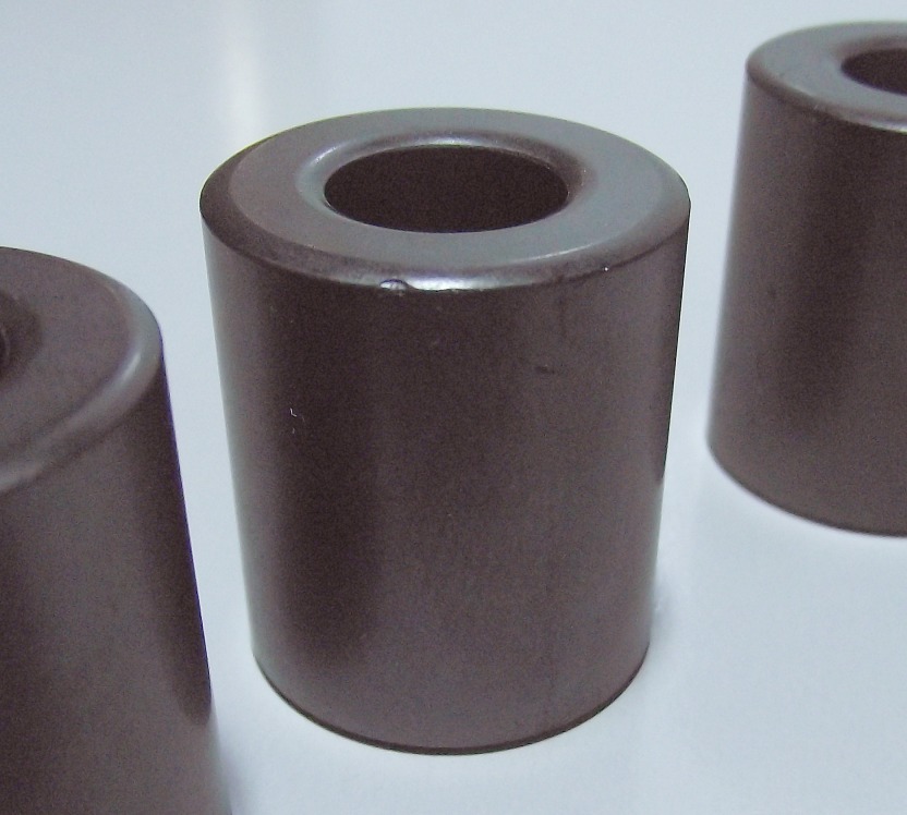 Ferrites are a type of ceramic made from iron and other oxides and come moulded into different shapes. The material combination is called a ‘mix’.
The characteristics of these mixes determine where and how they should be used. When a wire passes through or near ferrite materials, it effectively adds resistance to that wire at radio frequencies, but this resistance effect varies with the frequency applied to the wire.
Every ferrite has its own characteristic impedance curve allowing it to absorb unwanted RF currents before reaching your receiver or appliance.
Unfortunately, you can’t tell what that working curve is going to be just by looking at it.
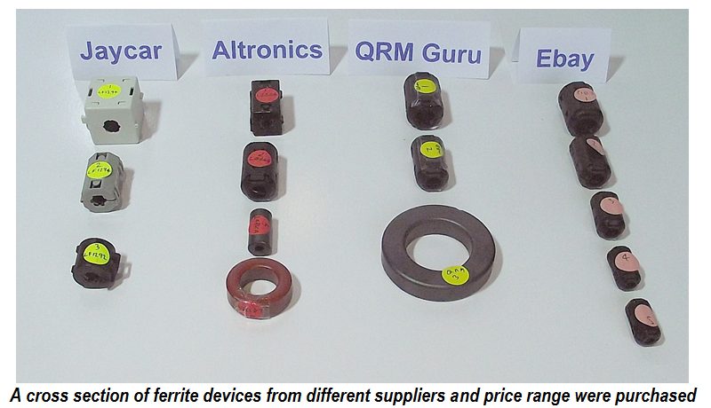
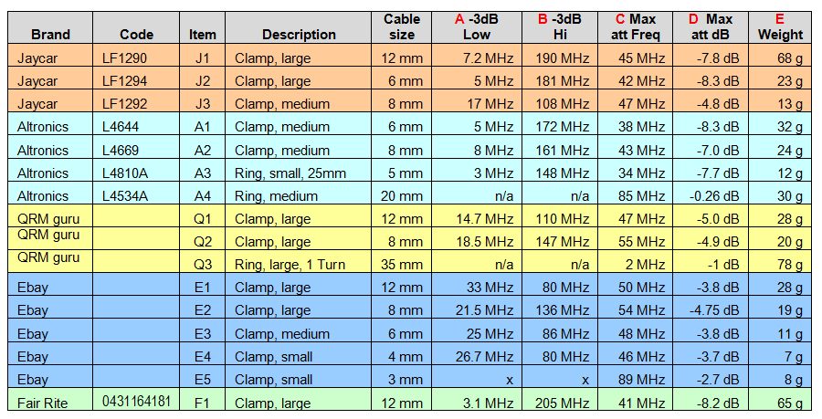
For this experiment, we purchased sample ferrites from the Australian retailers Jaycar and Altronics. We compared these with samples of similar size from the QRM Guru ferrite kits, then further compared all of these with some cheap ‘no-name’ ferrites purchased from eBay.
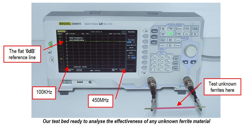
Testing methodology is important. We used a spectrum analyser with a tracking generator. The spectrum analyser shows gain or loss of radio frequencies between any two points on the radio spectrum. Our unit has capability to scan the radio spectrum from 10KHz to 1.5 GHz, but in this trial, we profiled these ferrite devices between 100KHz and 450MHz.
The tracking generator creates a small signal that regularly sweeps between two frequencies we are monitoring at a very controlled level. We are then able to couple from the tracking generator to the spectrum analyser via a small brass rod, which will become our test wire. First we ‘normalise’ to compensate for any stray capacitance and inductance around our test area. A flat yellow line represents zero dB. This line becomes our reference point before filtering is added. When any unknown ferrite is added to the test conductor, we measure a clear plot showing the unique characteristics of that item.
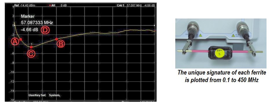
With this arrangement we examined a graphic plot of each sample, then recorded five unique values which identify its effectiveness. We looked at :
- (A) The lowest frequency where the item drops below the -3dB (half-signal) point.
- (B) The highest frequency where the curve crosses the -3dB point
- (C) The frequency (MHz) where the greatest attenuation takes place
- (D) The maximum degree of attenuation (peak –dB) that takes place.
- (E) The weight of each ferrite item. (in grams)
Not all characteristics are being tested here
It should be noted that this article is focused on using ferrites for noise reduction only. In this role the energy being absorbed is not great. Where ferrites are used in high-current environments, such as in a transmitter balun, there will be an RF power threshold where they can no longer effectively absorb energy and their characteristics will begin to distort.
The overheating and saturation effects of high current applications are not a part of this study.
Study Results
The table below contains the raw results of our assessment, grouped in order of supplier, then size. The figures can be difficult to digest in this form, but we can take away some very important findings from this test data.
Branding vs Price
The first significant observation is that they all worked. Regardless of the source, none of the samples tested were fake or defective. They were all capable of suppressing radio frequencies to a greater or lesser degree. This is reassuring, as you can never prove authenticity just by looking at a ferrite.
From these samples, we can surmise that regardless of their source, all of these clamp-on ferrites will provide at least some degree of effectiveness in the shack.
Ferrite Mixture Type
The next observation (with the exception of the Altronics Iron Core ring) is that all of these materials are composed from a similar mix of ferrite material. The absorption curves were all a reasonable match to Mix 43. This indicates that their application is appropriate for HF and low VHF frequencies. (The Altronics ring L4534A was purchased with the rest of the ferrites, but it does not qualify as a ferrite device. It is a powdered iron object with different characteristics. We left it in the test for contrast and will provide separate comment on these devices.)
Size vs weight correlation of ferrite clamps
Clamp-on ferrite devices come in a variety of different physical sizes and shapes. It is reasonable to think that bigger ferrites work better than smaller ones, but is this actually the case? We sorted our samples by weight and plotted this chart to see how closely the degree of absorption of RF energy followed the physical weight of each sample.
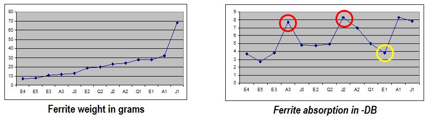
 The answer appears to be”partially yes”. Generally, heavier ferrites will out-perform lighter versions, but there were a couple of exceptions that did very well.
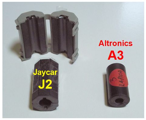
The Altronics solid ring L4534A (A3) outperformed clamps of similar weight, as did the Jaycar LF1294 (J2). Both are circled in red in the chart above.
There is a correlation between ferrite effectiveness and wall thickness. Both circled examples had a relatively small internal wire opening, which made for a thicker clamp wall. This equates to a higher density of ferrite material around the single conductor, giving superior performance.
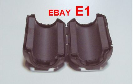 Conversely, sample E1 from eBay was a physically large clamp, but it catered for a thick 12mm cable. This thinner wall thickness reduced effectiveness, as seen by the data point circled in yellow on the chart above.
This effect is not as bad as it first seems, so don’t necessarily shop only for thick-walled clamps. Examine some of the following sections in this article which explore the most effective ways to use ferrite clamps.
The final comment on the size of clamps was the observation that the very small clamp-on ferrites don’t have sufficient mass for good performance. The smallest of the eBay clamps (E5) didn’t even reach -3dB. Unless a friend gives you a lot of them for nothing, there is a lot to be said for aiming straight for medium and large clamps, or the results could be disappointing.
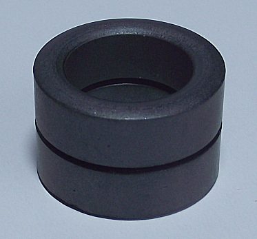
Are solid ferrite rings better than split rings?
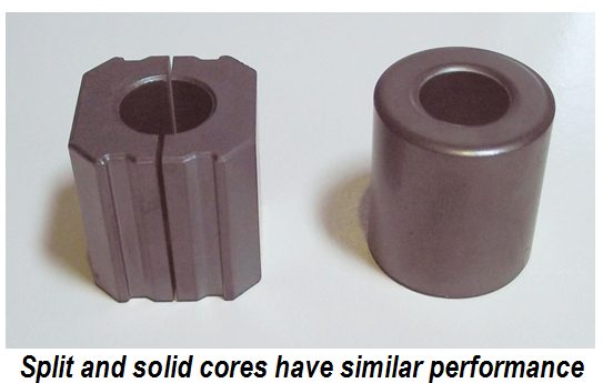 This turned out to be an easy question to answer. Two rings of similar weight, hole-size and ferrite mix were compared. One was solid and the other was split.
The results were almost identical when tested. This tells us that shopping for solid cores have no real advantage over split cores. However, the split ferrites can be applied to cables without having to remove connector plugs and this makes them a more practical purchase.
What’s the best way to use ferrites?
An important question to answer is “what is the optimum configuration for the application of ferrite clamps“. It’s easy to imagine that two clamps are better than one, but how much better?
For this exercise we focused our attention on the QRM Guru clamps (Q2) designed for 8mm wire.
Compare the following screen captures and images of one and two clamps:
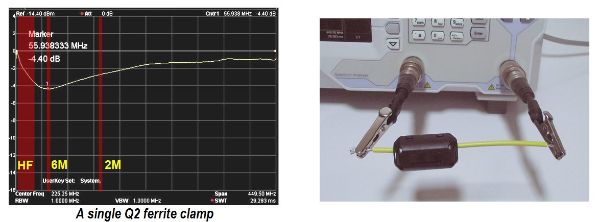
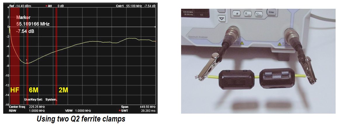
Unsurprisingly, doubling up on the clamps gives an additional 3dB of RF absorption. At 55 MHz the peak absorption jumped from -4.40 dB to -7.54 dB. This tells us that if one clamp on its own does not quite do the job, then add another for improved performance. Be aware that to achieve a further 3dB, you must double again from two to four units.
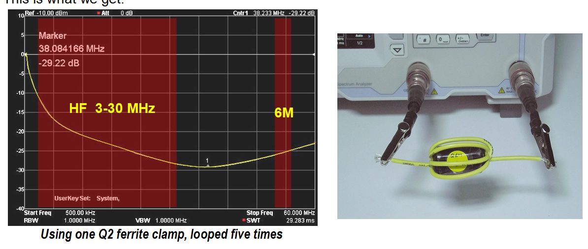
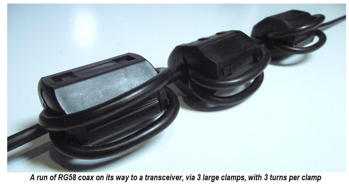
Next, we explore the effectiveness of looping a wire through a clamp more than once. This can only work where there is sufficient slack in the cable, and where the hole in the core is large enough to accept additional turns.
Here is what happens:
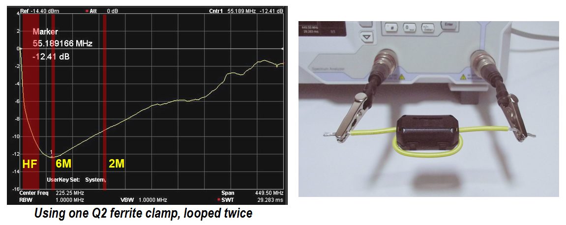
This is a very interesting result showing that the single extra turn through the core increases absorption from -4.4dB to a huge -12.41 dB. This 8 dB increase makes a single clamp provide the same effectiveness of around six such clamps on the same wire.
Want to see some case studies covering off the use of ferrites? Click on the links below
Why adding turns makes ferrites much more effective
This effect is not really a mystery when we break down what’s happening. When we add ferrite to a wire, we are effectively adding series resistance to that wire, but this resistance effect varies with frequency. At steady DC, the ferrites have no effect, but as an AC signal is applied a resistance is developed within the wire surrounded by the ferrite material. The higher the frequency, the greater the increased resistance. This resistance is also affected by the type of ferrite material, its volume, and its distance from the wire concerned.
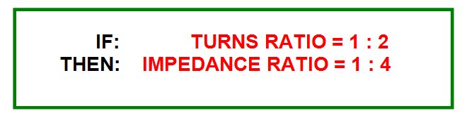
When we increase the windings through a core, we begin to invoke conventional transformer theory as well. As happens in power transformer calculations, the impedance ratio is always the square of the turns ratio. So increasing turns through the core by x2 lifts its impedance (and attenuation effect) by x4. A x4 increase equates to a 6dB increase. In our example above we had a larger 8dB change. This was because on the first turn, where the wire just passed through a clamp, it was not in contact with the ends of the clamp. Hence the first complete loop through the core provides more benefit than just one turn.
Earlier we observed that thin wall clamps had poorer performance than thick wall clamps. However, if the reduced wall thickness then allows multiple turns through the clamp, it will more than make up for the initial poor response afforded by a single wire passage.
The big takeaway from this observation is to insert the maximum possible turns through any ferrite clamp. This is always going to be cheaper and more compact than adding extra clamps to the same wire. If more suppression is needed, perform both actions.
Ferrite clamps vs ferrite rings
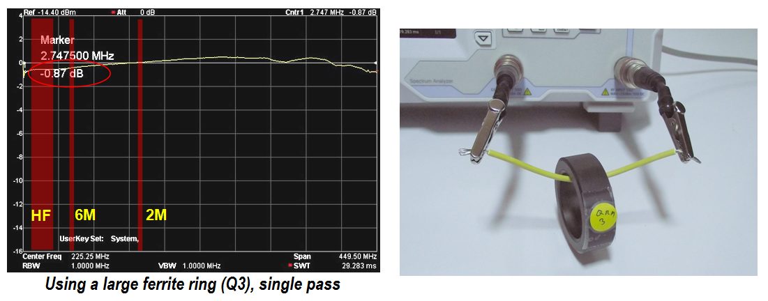
Initial test results of ferrite rings showed poor performance compared to clamps when a single wire was passed through a ring. This does not mean that ferrite rings are a poor choice. Ferrite rings are a convenient way for a large cable to achieve multiple turns and high exposure to the ferrite material.
In the example below we can see the effects of a single wire passing through a large ferrite ring both once and then in another experiment using four complete turns.
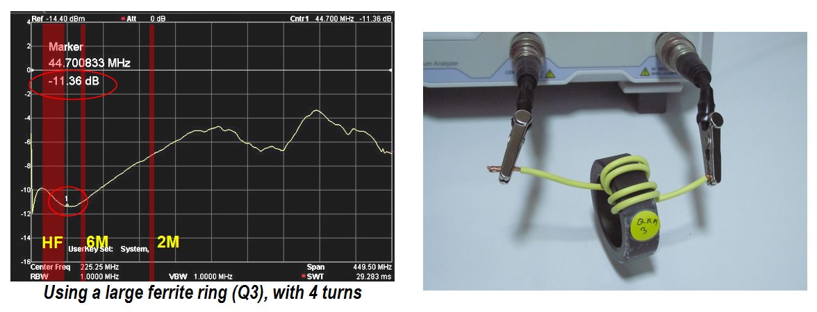
Certainly, there is ample room for adding even more windings, but the rapid escalation of HF absorption becomes very apparent from just four turns.
Some unpredictable dips and distortions begin to appear in the plot at VHF and UHF frequencies. This is mostly due to increased stray capacitances and resonance effects of large rings interacting with the wiring.
Ferrite rings become very practical choices where cables are thick and a lot of suppression is needed. There is a lot of ferrite volume in the larger rings, permitting a lot of energy absorption.
 Stacking rings before windings are applied are another excellent way of increasing that volume and overall effectiveness.
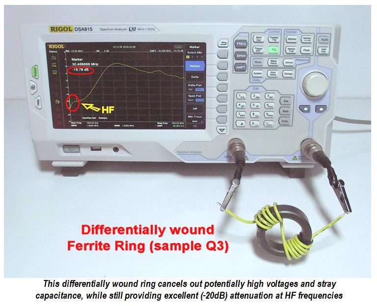
One precautionary comment: A high turns-ratio on a ferrite ring also generates high circuit voltages if there is significant energy being dissipated. This effect can be cancelled out without affecting absorption if the ring has balanced windings between two sides of the ring
How important is it to get the right Mix?
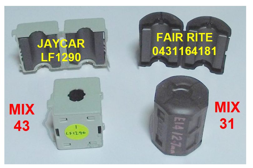
As previously described, ferrite products are created with different mixture profiles. These different mixes absorb RF energy in different parts of the spectrum. Thus far we have examined a range of common ferrite clamps and rings which profile as ‘Mix 43’, which is a common, general purpose filter. However some operators are keen to obtain maximum effect on lower HF bands and in this area Mix 31 is reputed to be better. This mix is generally harder to get and more expensive, so it would be nice to know if it is worth the effort.
In this final experiment we purchased some genuine Fair Rite samples graded as Mix 31. This was a very close physical match in size, shape and weight to the Jaycar LF1290 with its Mix 43 profile. A good physical match was important for realistic comparisons at HF frequencies.
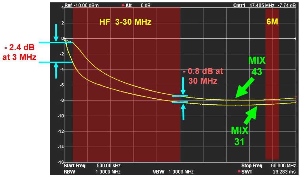
The results confirm that the Mix 31 ferrites can absorb RF at lower frequencies than the more readily available Mix 43 composition. With the single passage of a conductor at 3MHz there was a measurable absorption difference of 2.4 dB. These two curves quickly begin to converge with a rise in frequency. At 30 MHz the difference was a scant 0.8 dB. By 150 MHz the two lines follow a near-identical path.
On the 80 metre HF band, the Fair Rite ferrite with its lower mix value delivers superior results, but the conventional Jaycar sample is not far behind. As seen with our previous measurements, absorption effects will compound where multiple turns of conductors are applied.
In practice, a single passage of cable through either type of clamp would barely create any discernible difference in Common Mode noise. Multiple turns are needed. The success of any good filtering exercise will therefore be governed by the number of turns that may be applied to a clamp, individually or as part of a chain of ferrite devices.
Summary
Ferrites have an important role to play in suppressing RF noise. These experiments and tests have illustrated the underlying science behind the practical application of ferrites in your desire to eliminate QRM. Some of the mystery surrounding ferrites have also be addressed. Much has been written on this topic and many detailed documents are available for those who wish to dig a little deeper. For most operators, this article will provide sufficient information to get started.
All ferrite devices exhibit a curve and a frequency where they are at their most effective. Just because the peak frequency is not where you wish to operate, doesn’t mean that the device won’t be fit-for-purpose in other parts of the spectrum. It’s all about having sufficient filtering to do the job at hand without blowing the budget.
As always, it is good to share experiences and achievements with others, so if you have a success story in the elimination of interference with ferrite clamps and rings, please forward notes to [email protected]
Thanks Ian VK3BUF for a practical insight into this complex topic. And thanks also to Leigh VK5KLT for conducting a peer review.
Want to see some case studies covering the use of ferrites? Click on the links below
Ian VK3BUF: “The Effectiveness of Ferrites”
Josh KI6NAZ: “For most of us, RFI is around us all the time“.
Peter VK3YE: “The best thing you can do for your ham station“